ESP8266 Getting Started with Arduino IDE
A guide to getting started with the ESP8266 with the Arduino IDE
This assumes that yo have a NodeMCU type board with the Silicon Labs CP2102 USB to UART Bridge. These boards are convenient because they can be connected directly to your computer for progamming and serial console.
First install the Silicon Labs CP2102 USB to UART Bridge driver for your operating system.
Then follow the instructions here to add the ESP8266 board to the Arduino IDE.
You should test the IDE using the Blink example. File>Examples>ESP8266>Blink
This will blink the Red LED on the Node MCU board. For more on the attached LEDs
To upload the code you need to select the following settings:
- Select the correct board Tools>Board>Node MCU 1.0 (ESP-12E Module)
- CPU frequency 80MHz
- Set the programmer baud rate to 115200 Tools>Upload Speed>115200
- Choose the port that the board is attached to Tools>Port on the Mac this will be /dev/cu.SLAB_USBtoUART
- Then click Upload
If you get the following warning and the code fails to upload.
warning: espcomm_sync failed
error: espcomm_open failed
You will need to put the board into flash mode manually. To do this press and hold the Flash button on the NodeMCU board then press and release the Reset button, finally release the Flash button. You should then be able to successfully upload the code.
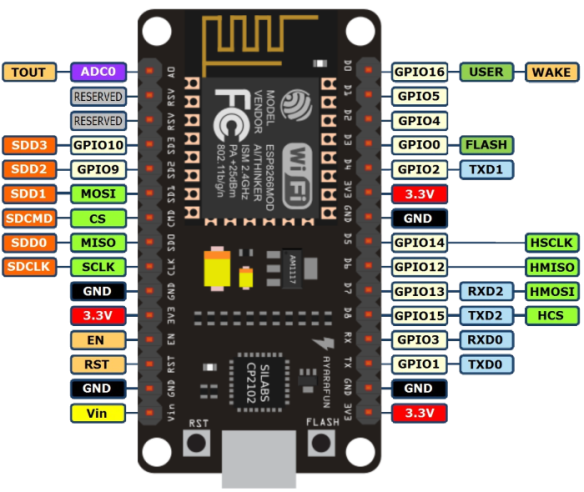
NodeMCU on board LEDs
The NodeMCU board and the ESP8266MOD modules from AI-THINKER both have LEDs on them. The blue LED near pin 22 on the ESP8266MOD-12E module is connected between Vcc and GPIO2 (TXD1) labelled D4 on the NodeMCU 1.0 Board. The Blue (or Red) LED on the NodeMCU Board is connected between Vcc and GPIO16 labelled D0 on the NodeMCU 1.0.
Note GPIO0 is also attached the the external flash chip on the NodeMCU board so if you wish to attach an additional element to this pin make sure it does not pull this pin to ground, other wise the board will not boot the program from the external flash memory when the power is cycled.
Board as shown on the schematic for the NodeMCU 1.0 Board
File System Uploader
NodeMCU pin functions
 https://bennthomsen.files.wordpress.com/2015/12/nodemcu_pinout_700-2.png?w=150 150w, https://bennthomsen.files.wordpress.com/2015/12/nodemcu_pinout_700-2.png?w=300 300w, https://bennthomsen.files.wordpress.com/2015/12/nodemcu_pinout_700-2.png 700w" sizes="(max-width: 584px) 100vw, 584px" data-reader-unique-id="42" class="extendsBeyondTextColumn" style="max-width: none; margin: 0.5em auto; display: block; height: auto; width: 700px; margin-inline-start: -26.953125px;">
NodeMCU 1.0 board pin out. Credit Alex Bloggs
")
")


