ESP8266 Client-Server Wi-Fi Communication Between Two Boards (NodeMCU)
https://randomnerdtutorials.com/esp8266-nodemcu-client-server-wi-fi/
Learn how to establish a Wi-Fi communication (HTTP) between two ESP8266 NodeMCU boards to exchange data without the need to connect to the internet (you don’t need a router).
You’re going to set one ESP8266 as an Access Point (Server) and another ESP8266 as a Station (Client). Then, the server and the client will exchange data (sensor readings) via HTTP requests. We’ll program the ESP8266 boards using Arduino IDE.
 https://i0.wp.com/randomnerdtutorials.com/wp-content/uploads/2020/01/ESP8266-Client-Server-Wi-Fi-Communication-Between-Two-Boards.jpg?resize=300%2C169&quality=100&strip=all&ssl=1 300w, https://i0.wp.com/randomnerdtutorials.com/wp-content/uploads/2020/01/ESP8266-Client-Server-Wi-Fi-Communication-Between-Two-Boards.jpg?resize=1024%2C576&quality=100&strip=all&ssl=1 1024w, https://i0.wp.com/randomnerdtutorials.com/wp-content/uploads/2020/01/ESP8266-Client-Server-Wi-Fi-Communication-Between-Two-Boards.jpg?resize=768%2C432&quality=100&strip=all&ssl=1 768w" sizes="(max-width: 828px) 100vw, 828px" data-recalc-dims="1" loading="eager" data-reader-unique-id="7" style="max-width: 100%; margin: 0.5em auto; display: block; height: auto;">
In this example, we’ll send BME280 sensor readings from one board to the other. The receiver will display the readings on an OLED display.
If you have an ESP32 board, you can read this dedicated guide: ESP32 Client-Server Wi-Fi Communication.
Watch the Video Demonstration
To see how the project works, you can watch the following video demonstration:
Project Overview
To better understand how everything works, take a look at the following diagram.
 https://i1.wp.com/randomnerdtutorials.com/wp-content/uploads/2020/01/ESP8266-Client-Server-Project-Overview.jpg?resize=300%2C180&quality=100&strip=all&ssl=1 300w, https://i1.wp.com/randomnerdtutorials.com/wp-content/uploads/2020/01/ESP8266-Client-Server-Project-Overview.jpg?resize=1024%2C615&quality=100&strip=all&ssl=1 1024w, https://i1.wp.com/randomnerdtutorials.com/wp-content/uploads/2020/01/ESP8266-Client-Server-Project-Overview.jpg?resize=768%2C461&quality=100&strip=all&ssl=1 768w" sizes="(max-width: 828px) 100vw, 828px" loading="eager" data-reader-unique-id="22" style="max-width: 100%; margin: 0.5em auto; display: block; height: auto;">
- The ESP8266 server creates its own wireless network (ESP8266 Soft-Access Point). So, other Wi-Fi devices can connect to that network (SSID:ESP8266-Access-Point, Password: 123456789).
- The ESP8266 client is set as a station. So, it can connect to the ESP8266 server wireless network.
- The client can make HTTP GET requests to the server to request sensor data or any other information. It just needs to use the IP address of the server to make a request on a certain route: /temperature, /humidity or /pressure.
- The server listens for incoming requests and sends an appropriate response with the readings.
- The client receives the readings and displays them on the OLED display.
As an example, the ESP8266 client requests temperature, humidity and pressure to the server by making requests on the server IP address followed by /temperature, /humidity and /pressure, respectively (HTTP GET).
The ESP8266 server is listening on those routes and when a request is made, it sends the corresponding sensor readings via HTTP response.
Parts Required
 https://i1.wp.com/randomnerdtutorials.com/wp-content/uploads/2020/01/ESP8266-Client-Server-Interaction-Sensor-Readings.jpg?resize=300%2C169&quality=100&strip=all&ssl=1 300w" sizes="(max-width: 750px) 100vw, 750px" loading="eager" data-reader-unique-id="43" style="max-width: 100%; margin: 0.5em auto; display: block; height: auto;">
For this tutorial, you need the following parts:
- 2x ESP8266 Development boards – read Best ESP8266 Boards Comparison
- BME280 sensor
- I2C SSD1306 OLED display
- Jumper Wires
- Breaboard
You can use the preceding links or go directly to MakerAdvisor.com/tools to find all the parts for your projects at the best price!

Installing Libraries
For this tutorial you need to install the following libraries:
Asynchronous Web Server Libraries
We’ll use the following libraries to handle HTTP request:
- ESPAsyncWebServer library (download ESPAsyncWebServer library)
- ESPAsync TCP library (download ESPAsyncTCP library)
These libraries are not available to install through the Library Manager. So, you need to unzip the libraries and move them to the Arduino IDE installation libraries folder.
Alternatively, you can go to Sketch > Include Library > Add .ZIP library… and select the libraries you’ve just downloaded.
You may also like: DHT11/DHT22 Asynchronous Web Server with the ESP8266
BME280 Libraries
The following libraries can be installed through the Arduino Library Manager. Go to Sketch > Include Library> Manage Libraries and search for the library name.
You may also like: Guide for BME280 with ESP8266
I2C SSD1306 OLED Libraries
To interface with the OLED display you need the following libraries. These can be installed through the Arduino Library Manager. Go to Sketch > Include Library> Manage Libraries and search for the library name.
You may also like: Complete Guide for SSD1306 OLED Display with ESP8266
#1 ESP8266 Server (Access Point)
 https://i0.wp.com/randomnerdtutorials.com/wp-content/uploads/2020/01/ESP8266-Server-BME-280.jpg?resize=300%2C169&quality=100&strip=all&ssl=1 300w" sizes="(max-width: 750px) 100vw, 750px" data-recalc-dims="1" loading="lazy" data-reader-unique-id="107" style="max-width: 100%; margin: 0.5em auto; display: block; height: auto;">
The ESP8266 server is an Access Point (AP), that listens for requests on the /temperature, /humidity and /pressure URLs. When it gets requests on those URLs, it sends the latest BME280 sensor readings.
For testing, we’re using a BME280 sensor, but you can use any other sensor by modifying a few lines of code (for example: DHT11/DHT22 or DS18B20).
Schematic Diagram
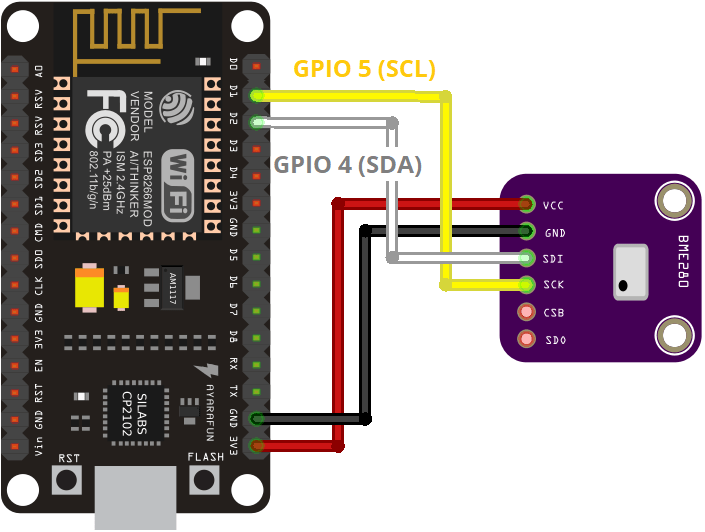
Wire the ESP8266 to the BME280 sensor as shown in the following schematic diagram.
 https://i2.wp.com/randomnerdtutorials.com/wp-content/uploads/2019/06/ESP8266-BME280-Arduino-IDE.png?resize=300%2C226&quality=100&strip=all&ssl=1 300w" sizes="(max-width: 705px) 100vw, 705px" loading="lazy" data-reader-unique-id="121" style="max-width: 100%; margin: 0.5em auto; display: block; height: auto;">
| BME280 | ESP8266 |
| VIN/VCC | 3.3V |
| GND | GND |
| SCL | GPIO 5 (D1) |
| SDA | GPIO 4 (D2) |
Arduino Sketch for #1 ESP8266 Server
Upload the following code to your board.
#include <ESP8266WiFi.h>
#include "ESPAsyncWebServer.h"

#include <Wire.h>
#include <Adafruit_Sensor.h>
#include <Adafruit_BME280.h>


const char* ssid = "ESP8266-Access-Point";
const char* password = "123456789";


Adafruit_BME280 bme;


AsyncWebServer server(80);

String readTemp() {
  return String(bme.readTemperature());

}

String readHumi() {
  return String(bme.readHumidity());
}

String readPres() {
  return String(bme.readPressure() / 100.0F);
}

void setup(){

  Serial.begin(115200);
  Serial.println();


  Serial.print("Setting AP (Access Point)…");

  WiFi.softAP(ssid, password);

  IPAddress IP = WiFi.softAPIP();
  Serial.print("AP IP address: ");
  Serial.println(IP);

  server.on("/temperature", HTTP_GET, [](AsyncWebServerRequest *request){
    request->send_P(200, "text/plain", readTemp().c_str());
  });
  server.on("/humidity", HTTP_GET, [](AsyncWebServerRequest *request){
    request->send_P(200, "text/plain", readHumi().c_str());
  });
  server.on("/pressure", HTTP_GET, [](AsyncWebServerRequest *request){
    request->send_P(200, "text/plain", readPres().c_str());
  });

  bool status;


  status = bme.begin(0x76);
  if (!status) {
    Serial.println("Could not find a valid BME280 sensor, check wiring!");
    while (1);
  }


  server.begin();
}

void loop(){

}
How the code works
Start by including the necessary libraries. Include the ESP8266WiFi.h library and the ESPAsyncWebServer.h library to handle incoming HTTP requests.
#include <ESP8266WiFi.h>
#include "ESPAsyncWebServer.h"
Include the following libraries to interface with the BME280 sensor.
#include <Wire.h>
#include <Adafruit_Sensor.h>
#include <Adafruit_BME280.h>
In the following variables, define your access point network credentials:
const char* ssid = "ESP8266-Access-Point";
const char* password = "123456789";
We’re setting the SSID to ESP8266-Access-Point, but you can give it any other name. You can also change the password. By default, its set to 123456789.
Create an instance for the BME280 sensor called bme.
Adafruit_BME280 bme;Create an asynchronous web server on port 80.
AsyncWebServer server(80);Then, create three functions that return the temperature, humidity, and pressure as String variables.
String readTemp() {
  return String(bme.readTemperature());

}

String readHumi() {
  return String(bme.readHumidity());
}

String readPres() {
  return String(bme.readPressure() / 100.0F);
}
In the setup(), initialize the Serial Monitor for demonstration purposes.
Serial.begin(115200);Set your ESP8266 as an access point with the SSID name and password defined earlier.
WiFi.softAP(ssid, password);Then, handle the routes where the ESP8266 will be listening for incoming requests.
For example, when the ESP8266 server receives a request on the /temperatureURL, it sends the temperature returned by the readTemp() function as a char (that’s why we use the c_str() method.
server.on("/temperature", HTTP_GET, [](AsyncWebServerRequest *request){
  request->send_P(200, "text/plain", readTemp().c_str());
});
The same happens when the ESP receives a request on the /humidity and /pressure URLs.
server.on("/humidity", HTTP_GET, [](AsyncWebServerRequest *request){
  request->send_P(200, "text/plain", readHumi().c_str());
});
server.on("/pressure", HTTP_GET, [](AsyncWebServerRequest *request){
  request->send_P(200, "text/plain", readPres().c_str());
});
The following lines initialize the BME280 sensor.
bool status;


status = bme.begin(0x76);
if (!status) {
  Serial.println("Could not find a valid BME280 sensor, check wiring!");
  while (1);
}
Finally, start the server.
server.begin();Because this is an asynchronous web server, there’s nothing in the loop().
void loop(){

}
Testing the ESP8266 Server
Upload the code to your board and open the Serial Monitor. You should get something as follows:
 https://i2.wp.com/randomnerdtutorials.com/wp-content/uploads/2020/01/access-point-ip-address-esp32-server.jpg?resize=300%2C155&quality=100&strip=all&ssl=1 300w, https://i2.wp.com/randomnerdtutorials.com/wp-content/uploads/2020/01/access-point-ip-address-esp32-server.jpg?resize=768%2C398&quality=100&strip=all&ssl=1 768w" sizes="(max-width: 803px) 100vw, 803px" loading="lazy" data-reader-unique-id="690" style="max-width: 100%; margin: 0.5em auto; display: block; height: auto;">
This means that the access point was set successfully.
Now, to make sure it is listening for temperature, humidity and pressure requests, you need to connect to its network.
In your smartphone, go to the Wi-Fi settings and connect to the ESP8266-Access-Point. The password is 123456789.
 https://i0.wp.com/randomnerdtutorials.com/wp-content/uploads/2020/01/connect-to-esp8266-access-point-smartphone.png?resize=300%2C289&quality=100&strip=all&ssl=1 300w" sizes="(max-width: 375px) 100vw, 375px" data-recalc-dims="1" loading="lazy" data-reader-unique-id="698" style="max-width: 100%; margin: 0.5em auto; display: block; height: auto;">
While connected to the access point, open your browser and type 192.168.4.1/temperature
You should get the temperature value in your browser:
 https://i2.wp.com/randomnerdtutorials.com/wp-content/uploads/2020/01/temperature-request-browser-esp32.png?resize=300%2C137&quality=100&strip=all&ssl=1 300w" sizes="(max-width: 750px) 100vw, 750px" loading="lazy" data-reader-unique-id="704" style="max-width: 100%; margin: 0.5em auto; display: block; height: auto;">
Try this URL path for the humidity 192.168.4.1/humidity:
 https://i2.wp.com/randomnerdtutorials.com/wp-content/uploads/2020/01/humidity-request-browser-esp32.png?resize=300%2C128&quality=100&strip=all&ssl=1 300w" sizes="(max-width: 750px) 100vw, 750px" loading="lazy" data-reader-unique-id="709" style="max-width: 100%; margin: 0.5em auto; display: block; height: auto;">
Finally, go to 192.168.4.1/pressure URL:
 https://i1.wp.com/randomnerdtutorials.com/wp-content/uploads/2020/01/pressure-request-browser-esp32.png?resize=300%2C132&quality=100&strip=all&ssl=1 300w" sizes="(max-width: 750px) 100vw, 750px" loading="lazy" data-reader-unique-id="714" style="max-width: 100%; margin: 0.5em auto; display: block; height: auto;">
If you’re getting valid readings, it means that everything is working properly. Now, you need to prepare the other ESP8266 board (client) to make those requests for you and display them on the OLED display.
#2 ESP8266 Client (Station)
 https://i1.wp.com/randomnerdtutorials.com/wp-content/uploads/2020/01/ESP8266-Client-OLED-Display.jpg?resize=300%2C169&quality=100&strip=all&ssl=1 300w" sizes="(max-width: 750px) 100vw, 750px" data-recalc-dims="1" loading="lazy" data-reader-unique-id="719" style="max-width: 100%; margin: 0.5em auto; display: block; height: auto;">
The ESP8266 Client is a Wi-Fi station that connects to the ESP8266 Server. The client requests the temperature, humidity and pressure from the server by making HTTP GET requests on the /temperature, /humidity, and /pressure URL routes. Then, it displays the readings on the OLED display.
Schematic Diagram
Connect an OLED display to your ESP8266 board as shown in the following schematic diagram.
 https://i2.wp.com/randomnerdtutorials.com/wp-content/uploads/2019/05/ESP8266_oled_display_wiring.png?resize=300%2C193&quality=100&strip=all&ssl=1 300w, https://i2.wp.com/randomnerdtutorials.com/wp-content/uploads/2019/05/ESP8266_oled_display_wiring.png?resize=768%2C495&quality=100&strip=all&ssl=1 768w" sizes="(max-width: 828px) 100vw, 828px" data-recalc-dims="1" loading="lazy" data-reader-unique-id="728" style="max-width: 100%; margin: 0.5em auto; display: block; height: auto;">
| Pin | ESP8266 |
| Vin | 3.3V |
| GND | GND |
| SCL | GPIO 5 (D1) |
| SDA | GPIO 4 (D2) |
Arduino Sketch for #2 ESP8266 Client
Upload the following code to the other ESP8266 (the client):
#include <ESP8266WiFi.h>
#include <ESP8266HTTPClient.h>
#include <WiFiClient.h>

#include <ESP8266WiFiMulti.h>
ESP8266WiFiMulti WiFiMulti;

const char* ssid = "ESP8266-Access-Point";
const char* password = "123456789";


const char* serverNameTemp = "http://192.168.4.1/temperature";
const char* serverNameHumi = "http://192.168.4.1/humidity";
const char* serverNamePres = "http://192.168.4.1/pressure";

#include <Wire.h>
#include <Adafruit_GFX.h>
#include <Adafruit_SSD1306.h>

#define SCREEN_WIDTH 128
#define SCREEN_HEIGHT 64


#define OLED_RESET     -1
Adafruit_SSD1306 display(SCREEN_WIDTH, SCREEN_HEIGHT, &Wire, OLED_RESET);

String temperature;
String humidity;
String pressure;

unsigned long previousMillis = 0;
const long interval = 5000;

void setup() {
  Serial.begin(115200);
  Serial.println();


  if(!display.begin(SSD1306_SWITCHCAPVCC, 0x3C)) {
    Serial.println(F("SSD1306 allocation failed"));
    for(;;);
  }
  display.clearDisplay();
  display.setTextColor(WHITE);

  Serial.print("Connecting to ");
  Serial.println(ssid);
  WiFi.begin(ssid, password);
  while (WiFi.status() != WL_CONNECTED) {
    delay(500);
    Serial.print(".");
  }
  Serial.println("");
  Serial.println("Connected to WiFi");
}

void loop() {
  unsigned long currentMillis = millis();

  if(currentMillis - previousMillis >= interval) {

    if ((WiFiMulti.run() == WL_CONNECTED)) {
      temperature = httpGETRequest(serverNameTemp);
      humidity = httpGETRequest(serverNameHumi);
      pressure = httpGETRequest(serverNamePres);
      Serial.println("Temperature: " + temperature + " *C - Humidity: " + humidity + " % - Pressure: " + pressure + " hPa");

      display.clearDisplay();


      display.setTextSize(2);
      display.setCursor(0,0);
      display.print("T: ");
      display.print(temperature);
      display.print(" ");
      display.setTextSize(1);
      display.cp437(true);
      display.write(248);
      display.setTextSize(2);
      display.print("C");


      display.setTextSize(2);
      display.setCursor(0, 25);
      display.print("H: ");
      display.print(humidity);
      display.print(" %");


      display.setTextSize(2);
      display.setCursor(0, 50);
      display.print("P:");
      display.print(pressure);
      display.setTextSize(1);
      display.setCursor(110, 56);
      display.print("hPa");

      display.display();


      previousMillis = currentMillis;
    }
    else {
      Serial.println("WiFi Disconnected");
    }
  }
}

String httpGETRequest(const char* serverName) {
  WiFiClient client;
  HTTPClient http;


  http.begin(client, serverName);


  int httpResponseCode = http.GET();

  String payload = "--";

  if (httpResponseCode>0) {
    Serial.print("HTTP Response code: ");
    Serial.println(httpResponseCode);
    payload = http.getString();
  }
  else {
    Serial.print("Error code: ");
    Serial.println(httpResponseCode);
  }

  http.end();

  return payload;
}
How the code works
Include the necessary libraries for the Wi-Fi connection and for making HTTP requests:
#include <ESP8266WiFi.h>
#include <ESP8266HTTPClient.h>
#include <WiFiClient.h>

#include <ESP8266WiFiMulti.h>
You need to create a WiFiMulti instance.
ESP8266WiFiMulti WiFiMulti;Insert the ESP8266 server network credentials. If you’ve changed the default network credentials in the ESP8266 server, you should change them here to match.
const char* ssid = "ESP8266-Access-Point";
const char* password = "123456789";
Then, save the URLs where the client will be making HTTP requests. The ESP8266 server has the 192.168.4.1 IP address, and we’ll be making requests on the /temperature, /humidity and /pressure URLs.
const char* serverNameTemp = "http://192.168.4.1/temperature";
const char* serverNameHumi = "http://192.168.4.1/humidity";
const char* serverNamePres = "http://192.168.4.1/pressure";
Include the libraries to interface with the OLED display:
#include <Wire.h>
#include <Adafruit_GFX.h>
#include <Adafruit_SSD1306.h>
Set the OLED display size:
#define SCREEN_WIDTH 128
#define SCREEN_HEIGHT 64
Create a display object with the size you’ve defined earlier and with I2C communication protocol.
Adafruit_SSD1306 display(SCREEN_WIDTH, SCREEN_HEIGHT, &Wire, OLED_RESET);Initialize string variables that will hold the temperature, humidity and pressure readings retrieved by the server.
String temperature;
String humidity;
String pressure;
Set the time interval between each request. By default, it’s set to 5 seconds, but you can change it to any other interval.
const long interval = 5000; In the setup(), initialize the OLED display:
if(!display.begin(SSD1306_SWITCHCAPVCC, 0x3C)) {
  Serial.println(F("SSD1306 allocation failed"));
  for(;;);
}
display.clearDisplay();
display.setTextColor(WHITE);
Note: if your OLED display is not working, check its I2C address using an I2C scanner sketch and change the code accordingly.
Connect the ESP8266 client to the ESP8266 server network.
while (WiFi.status() != WL_CONNECTED) {
  delay(500);
  Serial.print(".");
}
Serial.println("");
Serial.println("Connected to WiFi");
In the loop() is where we make the HTTP GET requests. We’ve created a function called httpGETRequest() that accepts as argument the URL path where we want to make the request and returns the response as a String.
You can use the next function in your projects to simplify your code:
String httpGETRequest(const char* serverName) {
  WiFiClient client;
  HTTPClient http;


  http.begin(client, serverName);


  int httpResponseCode = http.GET();

  String payload = "--";

  if (httpResponseCode>0) {
    Serial.print("HTTP Response code: ");
    Serial.println(httpResponseCode);
    payload = http.getString();
  }
  else {
    Serial.print("Error code: ");
    Serial.println(httpResponseCode);
  }

  http.end();

  return payload;
}
We use that function to get the temperature, humidity and pressure readings from the server.
temperature = httpGETRequest(serverNameTemp);
humidity = httpGETRequest(serverNameHumi);
pressure = httpGETRequest(serverNamePres);
Print those readings in the Serial Monitor for debugging.
Serial.println("Temperature: " + temperature + " *C - Humidity: " + humidity + " % - Pressure: " + pressure + " hPa");Then, display the temperature in the OLED display:
display.setTextSize(2);
display.setTextColor(WHITE);
display.setCursor(0,0);
display.print("T: ");
display.print(temperature);
display.print(" ");
display.setTextSize(1);
display.cp437(true);
display.write(248);
display.setTextSize(2);
display.print("C");
The humidity:
display.setTextSize(2);
display.setCursor(0, 25);
display.print("H: ");
display.print(humidity);
display.print(" %");
Finally, the pressure reading:
display.setTextSize(2);
display.setCursor(0, 50);
display.print("P:");
display.print(pressure);
display.setTextSize(1);
display.setCursor(110, 56);
display.print("hPa");

display.display();
We use timers instead of delays to make a request every x number of seconds. That’s why we have the previousMillis, currentMillis variables and use the millis()function. We have an article that shows the difference between timers and delays that you might find useful (or read ESP8266 Timers).
Upload the sketch to #2 ESP8266 (client) to test if everything is working properly.
Testing the ESP8266 Client
Having both boards fairly close and powered, you’ll see that ESP #2 is receiving new temperature, humidity and pressure readings every 5 seconds from ESP #1.
This is what you should see on the ESP8266 Client Serial Monitor.
 https://i0.wp.com/randomnerdtutorials.com/wp-content/uploads/2020/01/esp32-client-receive-sensor-readings.jpg?resize=300%2C176&quality=100&strip=all&ssl=1 300w" sizes="(max-width: 721px) 100vw, 721px" data-recalc-dims="1" loading="lazy" data-reader-unique-id="1733" style="max-width: 100%; margin: 0.5em auto; display: block; height: auto;">
The sensor readings are also displayed in the OLED.
 https://i1.wp.com/randomnerdtutorials.com/wp-content/uploads/2020/01/Display-Readings-OLED-ESP32-Client.jpg?resize=300%2C169&quality=100&strip=all&ssl=1 300w" sizes="(max-width: 750px) 100vw, 750px" data-recalc-dims="1" loading="lazy" data-reader-unique-id="1737" style="max-width: 100%; margin: 0.5em auto; display: block; height: auto;">
That’s it! Your two ESP8266 boards are talking with each other.
Wrapping Up
In this tutorial we’ve shown you how to send data from one ESP8266 board to the other using HTTP requests. This project can be very useful if you need to setup a wireless communication between two boards or more and you don’t have a router nearby.
For demonstration purposes, we’ve shown how to send BME280 sensor readings, but you can use any other sensor or send any other data. Other recommended sensors:
We have a similar tutorial for the ESP32 that you might find useful:
We hope you liked this tutorial. We’re preparing more tutorials like these. So, stay tuned and subscribe to our blog!
Thanks for reading.
")
")


